I’m going to start this post with a giant warning and disclaimer. Do not, under any circumstances, attempt to reproduce what I’m about to describe in this post unless you independently know exactly what you are doing. This post describes wiring up things to work with mains electricity, which will kill you if you make even one miswiring, or accidentally scrape an exposed metal surface that you’re supposed to stay away from. Publishing this post does not constitute an instruction on my part for you to go reproduce this, and if you choose to do so out of your own free will, I do not take responsibility for any results, short-term or long-term, including any personal injury, death, or loss of property that may occur as a result.
With that out of the way, let’s begin. In the summer of 2017, my first summer in Germany, I was forced to make a rather big purchase: an evaporative air cooler. Temperatures had spiked to over 30 degrees celsius on occasion, and I was actually managing to get sick from the heat. An evaporative cooler was both a practical and an economical solution to the problem. I could wheel it around, it didn’t take too much power, and I could put some frozen salt ice bags or orthopaedic gel packs into the water tank to cool the water down on those extra hot days.
For two summers, this worked great. On the third summer, the pump broke down.
Pretty much everywhere in Germany, the water is very hard. Calcification in the water tank, which I had neglected for the most part, had finally destroyed the submersible aquarium pump inside that pumped water into the evaporation mesh. So not only did I have to clean the water tank and flush out the piping with descaling fluid, I also had to replace the pump. So for the first time, I opened up the cooler, took out the pump and cleaned up whatever I could.
The first shock I had was when I looked at the label on the pump to find its ratings so that I could order a replacement. The pump ran directly off a 220V mains supply and was submerged in the water tank, where I had dipped my hand into on multiple occasions to check the water temperature while the pump was running. This was never going to do, so I ordered a 12V DC pump this time, with the same flow ratings, and something I found on Amazon called a 12V LED Transformer, which looked like it had what I wanted: a 220V AC input, a 12V DC output and rated for about 680mA of current. I double-sided taped the power adapter inside the dry section of the cooler, connected the new pump, and stayed cool for the most part of that summer.
But towards the end of that summer, this arrangement also failed. The pump was basically always running, even with the main unit switched off, which meant that the main control electronics had failed somehow. Additionally, when I took apart the unit again and inspected the “LED Driver”, it turned out it was using a capacitor divider to step down the AC voltage and then using a single diode to rectify it, plus an additional filter capacitor on the output. The voltage divider capacitors were leaking, and the pump was again calcified all the way through, so it would again need to be replaced.
So I had to consider: throw this one away and buy a better cooler, or try to replace the control electronics and get this unit running again? I briefly considered the first option, but my unit had adequate performance, it was the right size and the main fan worked. I also didn’t want to add more waste to a landfill somewhere. Also, I’m an electrical engineer by education (sort of anyway, my degree is in Computer Science & Engineering), so I should be able to fix this, right?
Anyway, the challenge was on.
The Teardown
The cooler was made somewhere in China, branded and sold as an in-house product by Conrad Electronics here in Germany, and I couldn’t just go out and order a new logic board from somewhere. I’d have to build my own control electronics, so the task I had on hand wasn’t particularly easy.
So I began by tearing down the whole cooler. The first thing that I started inspecting was the main fan motor. Now I know that wiring up AC motors isn’t easy (you need starter capacitors and special drive electronics to create enough torque to get the motor spinning in the right direction), and I assumed that the motor would be an AC induction motor and I’d need to buy a variable frequency drive to control the fan speed. What I found out was that the motor had 4 wires coming out of it, and it already had a capacitor built in, so none of those four wires needed to be wired to a capacitor.
My first instinct was that this was a 3-phase motor and one of the wires was for grounding the metal body. That assumption was quickly proven wrong when I realised that the whole unit just had a 2-pin plug for the mains supply. None of this was grounded.
Then I looked at the label on the motor. The wire colours were marked as L, M and H, and the black wire was COM. Could it really be that simple?
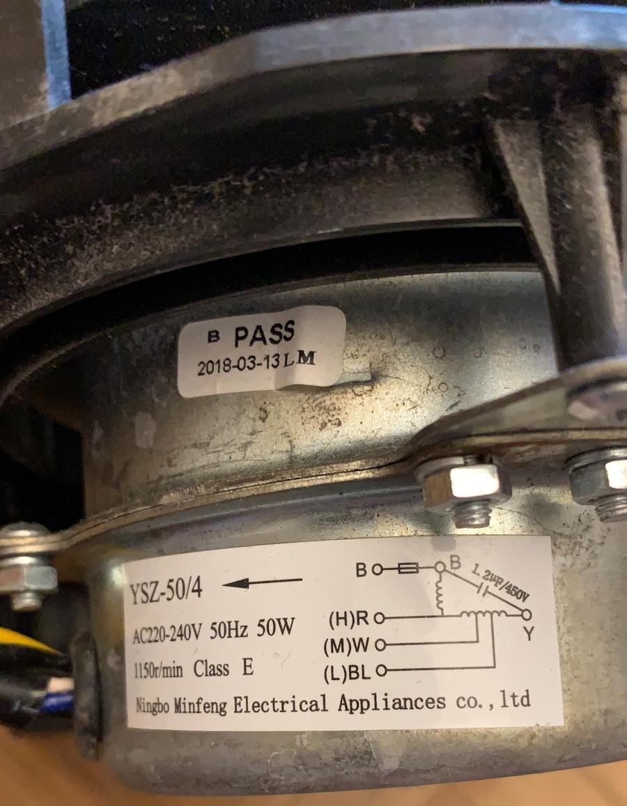
Turns out, it was. Apparently these motors are 3-speed AC motors of some sort, and these types of motors are pretty common in air conditioners and coolers, and even table fans which only have 3 speed settings. I should have guessed, since the control panel on the top of the cooler only had 3 options for “wind speed” - low, medium and high. And what’s more, wiring them up is dead simple: you just plug the COM (common) wire into the mains neutral, and then connect the mains hot line to whichever speed you want. I wouldn’t be able to control the speed of the fan on a continuous range, but I would definitely be able to change the speed easily.
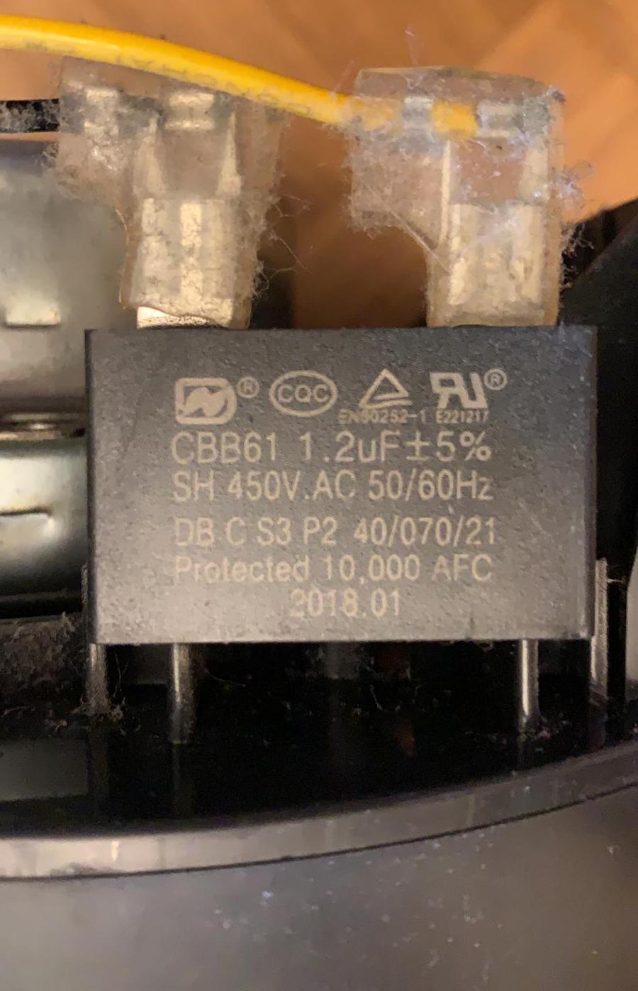
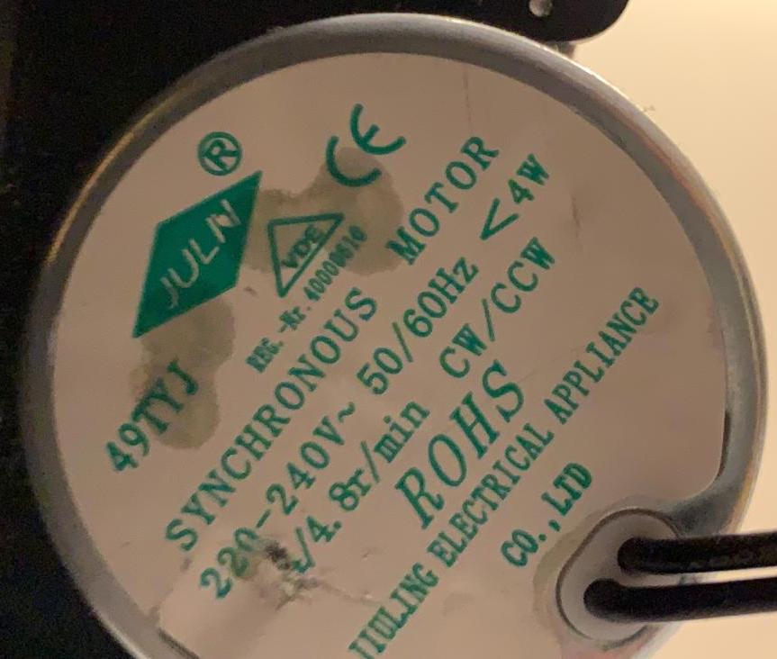
The next bit was the swing motor - a small motor attached to the vent slats in the front of the unit that swung the air direction from side to side. This was also a 220V AC motor, and about the size of a hockey puck. It had just two wires, so you’d only need to plug it in to mains the usual way.
The third component was of course the pump. I’d be buying a new one anyway, and I had the freedom to choose what voltage I wanted. I left that decision for later. Also in the water tank was what looked like a floating switch, which was mounted deep inside the tank, right at the bottom. This was the tank empty sensor, and with some multimeter testing, I figured out that this was normally open, and closed when floating. So wiring this up would just be a matter of connecting one side to the microcontroller voltage, one side to the input pin, and pulling the input down.
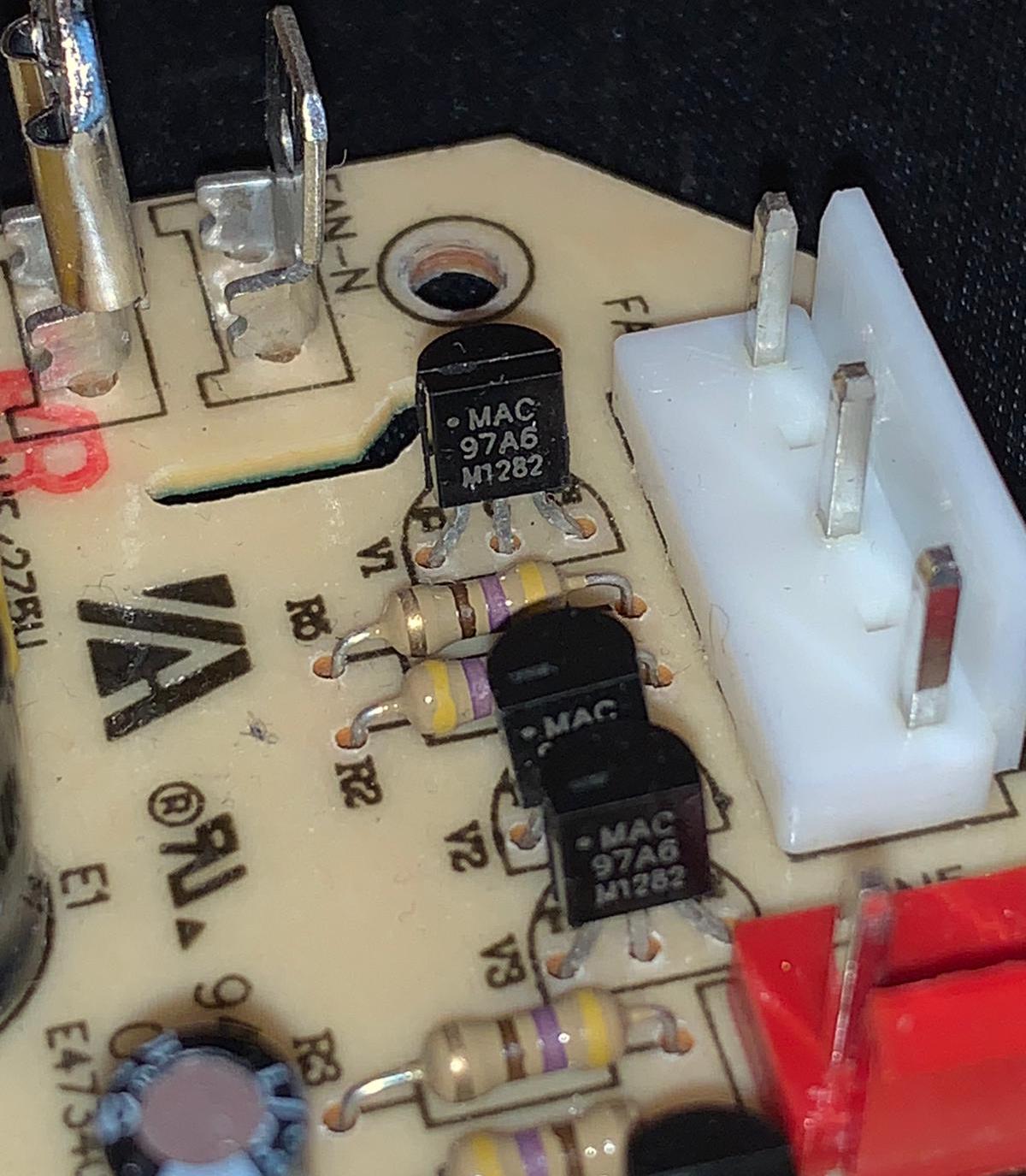
With all of this out of the way, I could finally turn my attention to the logic board itself. And this is where I got my second shock: apart from a tiny buck converter that supplied the tiny microcontroller on the board, the entire board was 220V AC. Not only that, there was no isolation, no grounding, and the switching elements were MAC97A6 triacs. Yes, that’s a triac in a TO-92 package (the same package you’d find BC547s in) switching mains electricity into a pretty hefty fan motor. No wonder this thing failed.
I’d do much better.
Shopping For Parts
I was never going to use triacs, especially such tiny ones, for switching mains power. From the very beginning, I planned to use relays. So the first item I went shopping for was a relay board. I needed at least 5 channels (3 for the different fan speeds, one for the swing motor and one for the pump), so I found a 8-relay board that I quite liked on Amazon. While it’s not mentioned in this product page, there’s a bunch of similar products (they all come from China and are likely made from the same design), and they had some nice properties that I loved: the inputs to the relays were opto-isolated (so you won’t kill your microcontroller with rush currents when actuating the solenoids), and while the relays required 5V DC for the switching, because the inputs were isolated they also worked with 3.3V logic inputs (just remove the jumper between the VCC and JDVCC pins on the bottom right of the board and supply 5V straight from a power supply to JDVCC). It’s also worth mentioning that the inputs are active low (if you’re using the normally open side of the relays, they’re active high if you’re using the normally closed side).
The next item on my list was the compute element. Now most sane people would use an Arduino or some sort of microcontroller. I needed something a bit more versatile. For what its worth, I have a few smart home accessories at home, and I’m more or less a full-time Apple user at this point. All my smart home devices are HomeKit compatible, and I wanted to be able to yell at Siri to control my cooler. So I needed something that would be comparitively easier to program, would have enough oomph to run a server to respond to HomeKit Accessory Protocol - which, by the way, is now a fully open protocol so anyone can create non-certified accessories and even create control apps for non-Apple platforms - requests and had WiFi. So of course, the only logical choice was a Raspberry Pi. I chose a Raspberry Pi 3 A+ - it’s smaller than the regular models but still has the full GPIO array, has only 512MB RAM (which seems enough, I mean, do I really need a 4GB air cooler), and is, most importantly, really cheap - at just 27 EUR.
Now that the Raspberry Pi dictated the DC voltage in the system (5V), I went ahead and ordered a 5V pump, and this time I ordered a rather hefty power supply (rated for 10A), because I’d be supplying the pump, powering the relays and of course powering the Pi from this supply, without any additional filtering.
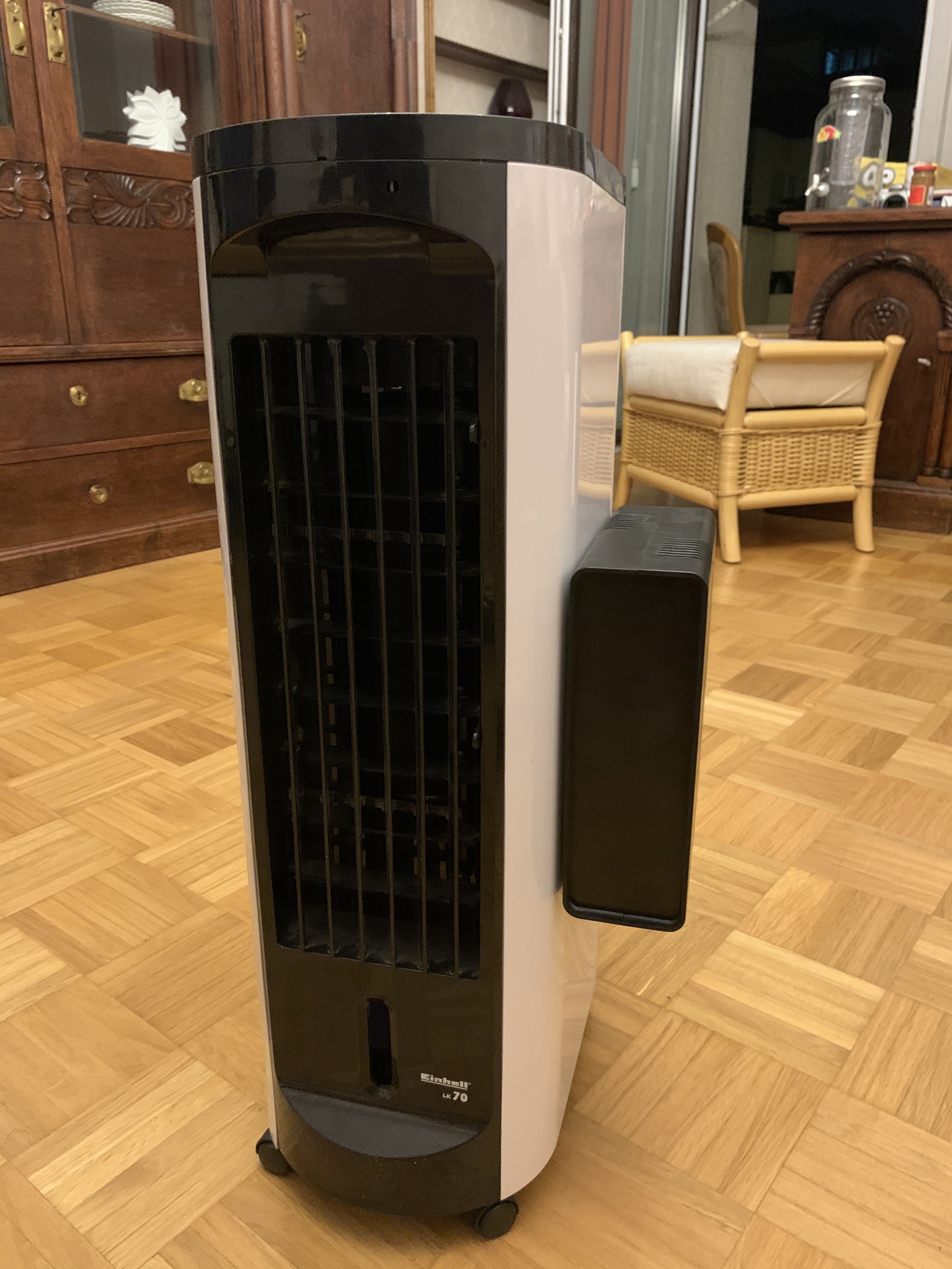
To round up the shopping, I ordered some jumper cables, a new power cable with a grounding wire, a plastic project case (there wasn’t enough space inside the cooler housing to fit all the additional electronics and wiring, so I decided to put everything in a separate box and fix it to the side of the cooler), and some 3M VHB Tape. If you’ve never heard of, or used VHB tape before, let me tell you a few things about it. VHB tape is your foam based double-sided tape, but it’s no run of the mill double sided tape. This thing is actually aerospace grade, and is used in aircraft and spacecraft to hold things together. Once attached, none of this is coming off, except when you actually want it to come off, at which point you can remove it without leaving any residue behind. Your locally store-bought “extra strength” double-sided tape is nothing compared to VHB tape, and you really shouldn’t have an engineering toolbox at home without some VHB tape in it.
Most of the construction is held together with VHB tape, including suspending the heavy power supply from the underside of the enclosure lid, attaching the electronics box to the side of the enclosure, and the submerged pump. The submerged pump is really why I had to use VHB tape - while I could have used the cheaper Tesa extra-strength stuff for the other things, I only trust real VHB tape to hold its strength underwater.
Wiring And Programming
I’m not going to go into too much detail about wiring except talking about the principles I followed. I also won’t go into too much detail about the programming for the simple reason that all the code is available for you to see on my GitLab account, but again I’ll talk about principles.
Let’s start with the wiring. The Raspberry Pi’s GPIO is 3.3V, and wiring up 5V relays to it is going to let out the magic smoke pretty quick. For this reason, having isolated inputs to the relay board comes in quite useful. I can wire up JDVCC to the 5V from my power supply, and wire up the GPIO directly to the inputs on the board, supplying VCC from the 3.3V pins on the Raspberry Pi itself. I don’t even need a separate 3.3V power supply.
Wiring up the tank empty sensor / switch also doesn’t actually need a pull-down resistor, because the pin can be pulled down in software. So again, just connect one end to a 3.3V pin on the GPIO, and the other end to your designated input pin.
I used the normally open side of the relays of course, and wired each speed of the fan to a separate relay (taking care in software that only one of these relays is activatable at any given time). These relays can switch both 5V DC and 220V AC (like all normal mechanical relays), so even the pump is switched with one of the relays.
On the software side of things, I initially started by using Python, with the built-in (to Raspbian) RPi.GPIO package to control my GPIO pins. I built a JSON API, and then a web app to work with this JSON API and turn individual elements on and off. I used Homebridge to bridge between the API and HomeKit. This never really worked well, and this multi-service architecture was needlessly complicated and I was never fully confident that there were no bugs, given that Python code was never statically analysed during compile-time (there is no compile-time).
So I learnt Go.
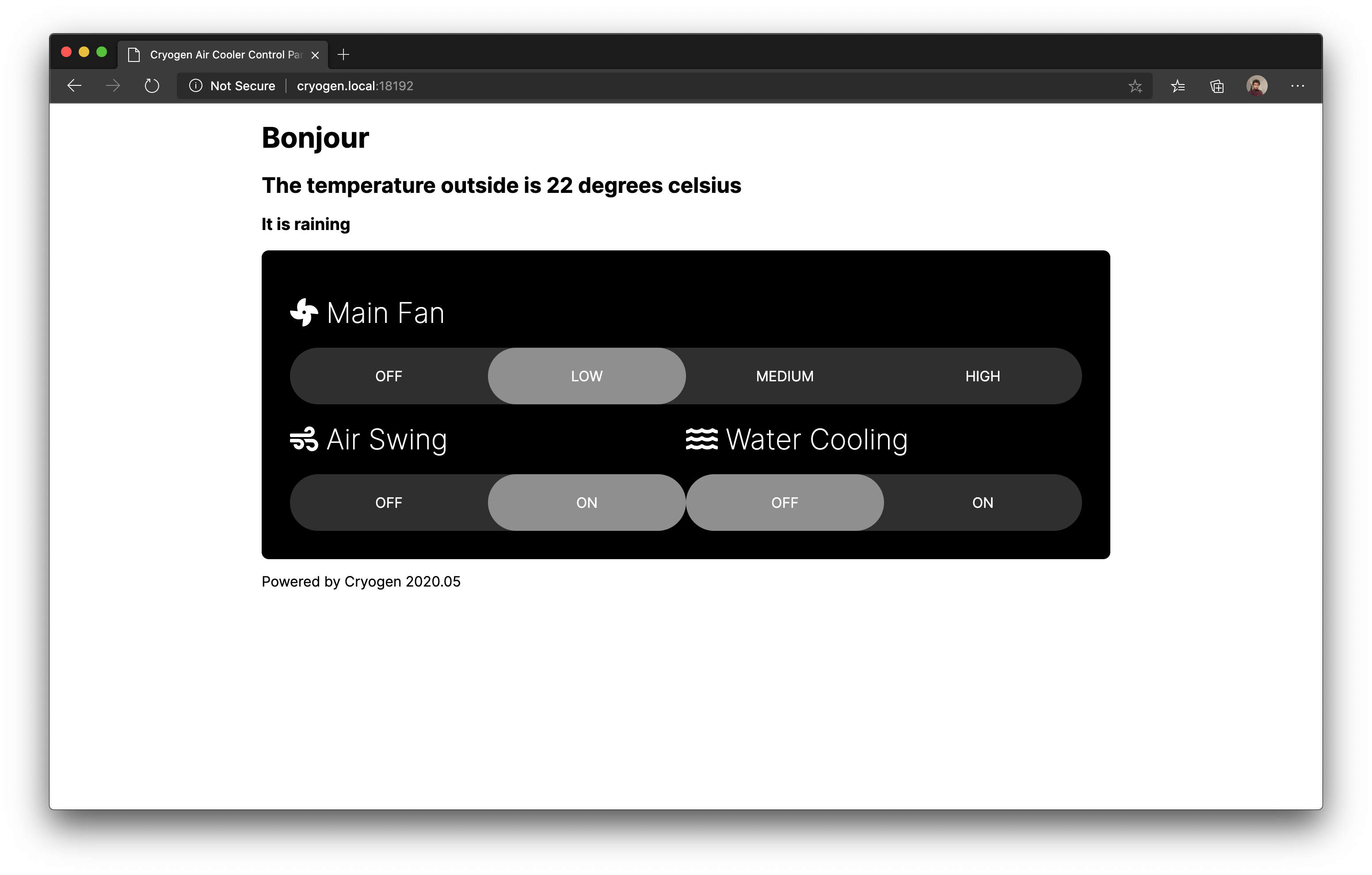
Re-writing the control software in Go was probably the most fun I had while working on this whole project. Go is so incredibly easy and fun to write (once you stop being annoyed at the enforced gofmt code-styling rules - which for some people I can see taking years). I went from not knowing Go at all to having a reimplimentation of my driver in 4 hours, the complete API in 24 hours, and it took me another day to implement the HomeKit bits, hooking directly into the driver and not bothering with the API. So now I have a Web UI, HomeKit integration, and a statically checked daemon that controls everything.
I used go-rpio to be able to control the GPIO pins. You can theoretically control your GPIO with just echo and cat by writing into and reading from the correct files under your /sys/class/gpio - and here’s an article in German explaining how to do that - but go-rpio memory-maps the /dev/gpiomem file and uses that to write directly into the bits of the CPU address space that control the GPIO pins, which also means that you don’t need to be root to run the driver and daemon, you only need to be part of the gpio group.
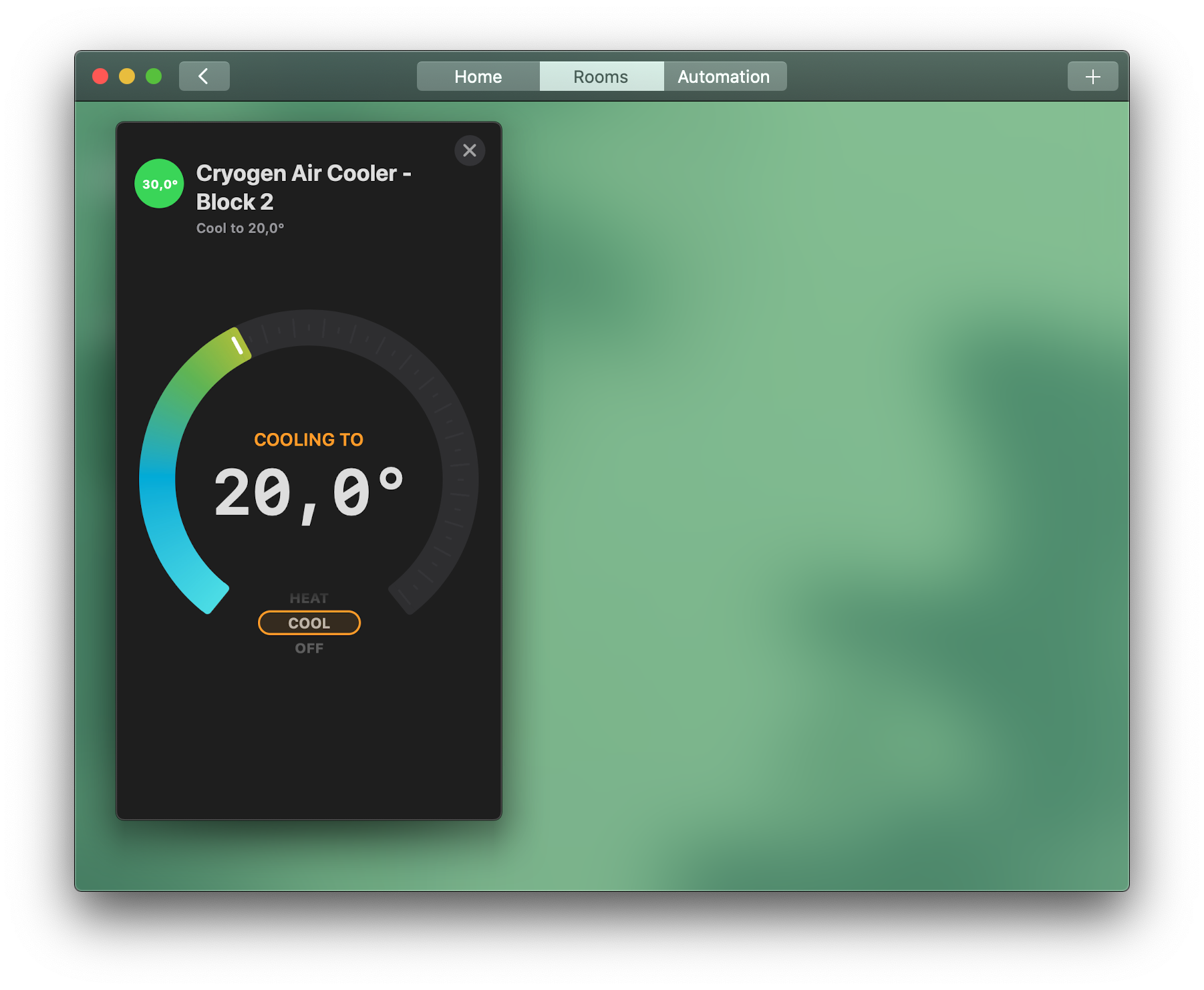
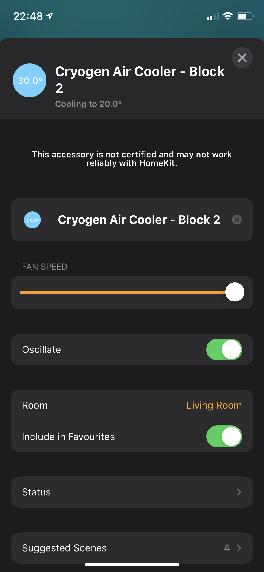
I used hc to be able to expose a HomeKit interface. HomeKit is conceptually a really simple protocol - an accessory has one or more services which it exposes, and every service is composed of different characteristics. If you want your device to be controllable by the Home app on iOS and macOS (and by yelling at Siri), you need to choose from a few Apple-defined combinations of accessories, services and characteristics. I decided to expose the cooler as an Air Conditioner, implementing the Heater-Cooler service, and implementing most of the optional characteristics. hc’s built-in accessory and service classes only implement the mandatory characteristics, so most of my code in hapservice.go is defining and building up my own service and accessory class.
The finaly bit of Go magic that I used was Goroutines. Goroutines are lightweight threads that are incredibly easy to implement (you just write a normal function with the go keyword preceeding it), and it took me about 5-10 lines of code to write a Goroutine that checks the water tank status every second and shut down the pump if it is running while the tank runs dry.
And finally, there’s the toolchain. Programming on a Mac and building for 64-bit ARM/Linux is simply a matter of setting the correct environment variables. I also strip the binaries and UPX-compress them (Go does produce some gigantic statically-linked binaries by default). My build command-line is something like:
$: GOOS=linux GOARCH=arm64 go build -ldflags="-s -w" && upx binaryname
Of course, this is only for test builds. I have GitLab CI set up on my repo, so every time I make a commit, it builds a new version of the binary within a minute and offers it up for download.
In Conclusion
I’m currently really happy with the way the cooler now works, and I find myself exclusively using HomeKit to control it. The Web UI definitely needs some work, and I might end up adding scheduling features to it, or automatic control based on the weather outside. I will definitely add a few temperature sensors - one for the water temperature, one for ambient temperature, and one probe right in front of the fan to measure effective wind temperature.
Because Go produces statically linked binaries and I need no operating system dependencies to run them, I was finally able to move to an Aarch64 (ARMv8) distribution, currently running Ubuntu Server 20.04. Yes, my cooler runs Ubuntu and I don’t know how I feel about it. Amongst other things (like having a more recent kernel and packages than Raspbian and being 64-bit), I also found it really easy to set up the network for first boot so that I never needed a monitor and keyboard and could just SSH in right after plugging the SD card in and turning on the machine. I also set up systemd-resolved to expose Multicast DNS so that even with a dynamic IP I can address my cooler with its hostname. The only thing I currently don’t like about Ubuntu Server is its forced use of Netplan, but I don’t know if I’m bothered enough to replace it with NetworkManager yet.
I hope you enjoyed reading about what I did during my ‘Rona lockdown, and remember kids, mains electricity is dangerous. Do NOT try this at home.